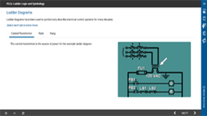
Ladder diagrams have been used to symbolically describe electrical control (PLC) systems for many decades. Early in the development of PLCs, it was decided to use ladder diagrams in their programming interface as well. This was done so that users of PLC systems would be able to see the program in a form that they were familiar with. Virtually all PLCs still use ladder diagrams. This course examines how PLCs use ladder diagrams to perform logic functions and the symbology involved.
Vector Solutions has a long history of providing industry-specific content for its customers. While this course and its content remain accurate and functional within our systems, the look and feel may not match our more modern offerings.
Describe parts of electrical ladder diagrams.
Identify common symbols used on ladder diagrams.
Describe using multiple devices on a rung.
Explain rung numbering and cross-references.
Explain differences between PLC and hard-wired ladder scans.
Describe JMP and jump to subroutine (JSR) instructions.
Industrial Libraries
- Industrial Complete
- Industrial Instrumentation & Control
- Industrial Maintenance
- Industrial Premium