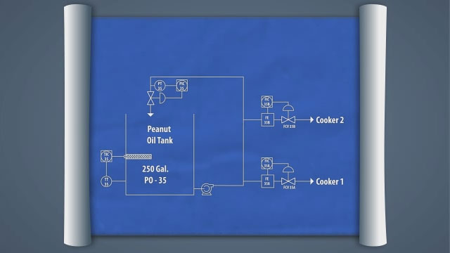
Process and Instrumentation Diagrams, also known as P&IDs, are basically maps meant to show process connections and equipment relationships pictorially. They are invaluable during the planning and installation of new equipment, maintenance planning and procedures, and when comparing as-installed controls to the original design. This module will discuss how P&IDs are used, how to read the symbols used on P&IDs, and a real world examples of a P&ID system.
•State the role that P&IDs play in safety
•Differentiate between diagram and physical placement
•Identify the major components of a P&ID sheet
•Describe the different types of symbols found on the P&ID sheet
•Follow a process flow by identifying the components, lines, and instrumentation
Industrial Libraries
- Convergence Industrial Maintenance Library
- Core Industrial Skills
- Industrial Complete
- Industrial Instrumentation & Control
- Industrial Maintenance
- Industrial Premium